Wood - Design
Full code checking can be performed on Dimension Lumber and Post and Timber size wood shapes based on the following codes:
- The 2024 edition of the NDS (with 2021 SDPWS and the 2018 or 2024 NDS Supplement)
- The 2018 edition of the NDS (with 2015 and 2021 SDPWS)
- The 2015 edition of the NDS
- The 2012 edition of the NDS
- The 2005/08 edition of the NDS
- The 2001 edition of the NDS
- The 1991 / 1997 editions of the NDS
- The 2014 edition of the CSA O86 Canadian wood design code
- The 2009 edition of the CSA O86 Canadian wood design code
Glu-Lams
Glu-Lams are treated as any other wood species and may be selected from the list of species on the Wood tab of the Materials spreadsheet.
Glulam Material Properties
Available Glulam Materials are per Tables 5A and 5C of the NDS Supplement and Table 6.3 of the CSA O86. When a Glu-Lam is selected, the grade will be listed as "na" or not applicable.
If you prefer to use a material that is not listed in the design code glulam tables, please enter the material type as a Custom Wood Species.
- Glu-Lams from Table 5A are always assumed to have the special tension laminations. Therefore, the Fbx value is not reduced.
- RISA is NOT applying
any of the footnotes to Table 5A and 5C at this time except for the following:
- Footnote #1 from Table 5A - For balanced materials Fbx- shall equal Fbx+ for the stress class.
- Footnote #3 from Table 5A - Fvx and Fvy are increased for Southern Pine Glulam materials.
- Commentary to CSA O86 Clause 6.2 notes that the Hem Fir glulam species listed in Table 6.3 are not common and therefore they are not included by default in RISA. If you prefer to use one of these materials, please enter it as a Custom Wood Species.
Glulam Dimensions
All Glu-Lam members should be dimensioned as "Full Sawn" using the format wXdFS (or wXdMFS for metric sizes), where "w" and "d" are the actual width and depth dimensions. If the size is entered as wXd without the FS designation, then the size will be assumed to be regular dimensional lumber.
Glulam Redesign Lists/ Optimization
RISA includes two redesign lists for Glu-Lams: Glu-Lam_Western for Western Species and Hardwoods (HW), and Glu-Lam_SouthernPine for Southern Pine (SP/SP).
Glulam Limitations
Please note that glulam design is not supported for the 91/97 NDS design code.
Custom Wood Materials & Structural Composite Lumber
To use a custom
wood material that is not part of the standard NDS or CSA O86 databases, you
need to define the custom design properties.
Custom Wood Properties
To access the Custom Wood Properties input window:
- Go to the Advanced ribbon.
-
Click the Custom Wood icon.

Click on image to enlarge it
The Custom Wood Species Database window opens.

Click on image to enlarge it
Follow the steps below that apply to what you want to do:
 Add a new custom wood
-
Click the Add button to open the Add Custom Wood Species window.

Click on image to enlarge it
-
In the Label box, type a name for the new custom wood.
-
In the Custom Wood Properties section, enter all the applicable properties, referring to the Allowable Stress Properties table for descriptions.
-
Click OK to save the new custom wood and close the Add Custom Wood Species window.
Edit an existing custom wood
-
Scroll through the list and click on the existing custom wood you want to modify.
-
Click the Edit button to open the Edit Custom Wood Species window.

Click on image to enlarge it
-
Enter the changes you want to make, referring to the Allowable Stress Properties table for descriptions.
-
Click OK to save your changes to the custom wood and close the Edit Custom Wood Species window.
The following table provides descriptions for each of the Allowable Stress properties.
Property
Description
Shear Stress (Fv)
CF
CF
The program defaults to 1.0, unless you manually enter a different value.
Specific Gravity
Specific Gravity represents the Specific Gravity applied to the custom wood.
-
- Click the Close button to close the Custom Wood Species Database window.


- Most wood materials (sawn lumber visually & mechanically graded, glulam, SCL, and LVL) are available in the current wood materials database. Please see the Wood tab of the Materials spreadsheet for more information.
- Due to the limited entries in the Custom Wood spreadsheet, Glulam members are always assumed to be balanced, uniform material:
- Fb is taken as the Fbx+, Fbx-, and Fby values for glulam design.
- Fv is taken as the Fvx and Fvy values for glulam design.
- E is taken as the Ex and Ey values for glulam design.
- Glulams will always use the CV volume factor equation per NDS Table 5C (this is the same equation as Tables 5A,5B, and 5D assuming that the material is not Southern Pine).
Create and Apply a Custom Wood Material
To create and apply custom material:
- Open the Materials spreadsheet.
-
Click on the Wood tab.

Click on image to enlarge it
- Select the last row in the spreadsheet and press Enter to create a new entry.
- In the Label box, type a name for the new custom property.
- Click on the Wood Type arrow and choose Custom from the list.
-
Do one of the following to define the custom species of the property you are adding.
-
Click on the Species arrow and choose from the existing custom species to include.
The list of available species is read in from the Custom Wood Properties window.
Note that you can click the ‘Edit’ button to open the Edit Custom Wood Species window in which you can modify the properties of this species.
-
Click the Add button to open the Add Custom Species window in which you can add a new custom species.
-
-
(Optional) Use the Design Properties options to change any of the default design properties for the custom wood you are adding.
Note that the Elastic Modulus Modifier Emod is a factor that is applied to the Young’s modulus modifier to reflect the NDS Appendix F criteria. This is not applicable to the CSA O86 design code.
-
Click OK to apply the new custom wood material and close the Edit Wood Material window.

For additional advice on this topic, please see the RISA Tips & Tricks webpage at risa.com/post/support. Type in Search keywords: Custom Wood Species.
Wood Design Parameters
The Wood Design Parameters spreadsheet records the design parameters
for the timber code checks and may be accessed by selecting

Click on image to enlarge it
These parameters are defined for each member.
Wood Design Parameters
|
Parameter |
Description |
|---|---|
|
Label |
The Label column lets you assign a unique Label to all of the members. Each label must be unique, so if you try to enter the same label more than once you get an error message. |
|
Shape |
The member Shape (or Section Set) column value is listed for reference only and can not be edited, as it is dictated by the entry in the ‘Section/Shape’ column on the Primary tab. |
|
Length |
The |
|
See the Unbraced Lengths topic. |
|
|
See the Unbraced Lengths topic. |
|
|
Adjustment Factors |
Please see below for information about the various wood adjustment factors. |
|
See the Unbraced Lengths topic. |
Timber Design Adjustment Factors
The NDS has a number of adjustment factors that are applied to the various allowable stresses to determine the capacity of the member. The adjustment factors are summarized in section 2.3 of the code. The following topics help to summarize how adjustment factors are obtained and used.
- Cb (Bearing Area Factor), CT (Buckling Stiffness Factor), Cc (Curvature Factor), CI (Stress Interaction Factor), and Cvr (Shear Reduction Factor) are NOT used in the RISA analysis.
- If you are using the Canadian CSA O86 design code, see the section below for the CSA adjustment factors.
Timber Design CD (Load Duration Factor- NDS)
CD is the Load Duration adjustment factor used for ASD codes. It is entered on the Load Combinations spreadsheet for each load combination for which you want wood code check results. The CD factor must be entered for each individual load combination because the CD factor is dependent on the types of loads that are applied in each load combination. Therefore, different load combinations could have different CD factors. For example, per the NDS 2024 specification, a load combination that had only dead load, would have a CD factor of “0.9”, while another combination that was comprised of dead load plus wind load would have a CD factor of “1.6”.
The CD factor will only be applied to wood code checks on wood members. See Table 2.3.2 in the NDS 2024 specification for the CD factors to be applied for typical loads. Appendix B has additional information about the Load Duration Factor.
Timber Design Cm (Wet Service Factor)
Cm is the Wet Service adjustment factor. It is applied when you check the Cm checkbox in the Materials Spreadsheet.
Timber Design Ci (Incision Factor- NDS)
Ci is the Incision factor per Table 4.3.8 of NDS code. It is applied when you check the Ci checkbox in the Materials Spreadsheet.
Timber Design Ct (Temperature Factor)
Ct is the Temperature adjustment factor. It is calculated internally based on the wood Temperature value set on the Codes tab of Model Settings. See section 2.3.3 of the NDS 2024 for more information on this factor.
Timber Design CP and CL (Column/Beam Stability Factors - NDS)
The Column Stability Factor, CP, and the Beam Stability Factor, CL,
are calculated internally. These calculated values are shown on
the Wood tab of the
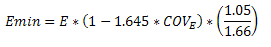
The value of Emin used for the calculation of these factors is calculated using equation D-4 from appendix D of the 2024 NDS. For some members (especially for glulams) this equation may produce a slightly more accurate value of Emin that shown in the NDS tables.
Timber Design CF (Size Factor- NDS)
CF is the Size adjustment factor. It is applied automatically when you assign a wood shape from the NDS shape database. See Tables 4A, 4B, 4D, and 4E in the NDS supplement for information on the CF factor.
Timber Design CV (Volume Factor)
CV is the Volume adjustment factor. It is applied automatically when you assign a glulam or SCL material member. The user can override the calculated value by manually entering the factor on the Wood tab of the Members Spreadsheet.
- In the calculation of CV, RISA takes L as the full length of the member. This is a conservative assumption.
- This factor is not available for the NDS 1991/1997 design option.
Timber Design Cfu (Flat Use Factor)
Cfu is the Flat Use adjustment factor. It is automatically applied to the weak axis allowable bending stress when weak axis moments are present.
For sawn lumber, in addition to the typical adjustment to weak-axis bending stress noted above, the flat use factor is also applied to the adjusted modulus of elasticity (E') and the adjusted modulus of elasticity for beam and column stability calculations (E'min) when minor-axis moments are present. Refer to NDS 2024 Table 4.3.1, Footnote 1 for more information.
Timber Design Cr (Repetitive Factor)
Cr is the Repetitive Member adjustment factor. This factor specifies if the beam is one of a group of repetitive members. This design parameter can be set on the Wood tab of the Members Spreadsheet. If you put a check in the Cr field, a factor of 1.15 will be applied to beam members that are 2" to 4" thick. See the section 4.3.9 of the NDS 2018 for information on this factor.
- This flag will be ignored for a NDS shape that is thicker than 4".
- A value of '1.0' will be used for Wood Products.
- Different restrictions apply to the use of the Cr factor for Structural Composite Lumber and Glu-Lams.
Timber Design CH (Shear Stress Factor)
CH is the Shear Stress adjustment factor. This design parameter can be set on the Wood tab of the Members Spreadsheet. If left blank the program will use a default value of 1.0. See the tables in the NDS supplement for information on other CH factors.
- The CH factor is only available for the 1991/1997 NDS option. For other codes, this entry will be ignored.
- Only tables 4A, 4B, and 4D are used.
Timber Design Cf (Form Factor)
Cf is the Form adjustment factor. It is applied automatically when designing by the NDS 91/97 or 2001 Specification and a 'Round' shape is selected from the NDS shape database. See section 2.3.8 in the NDS (91/97, 2001) for information on the Cf factor.
- This factor is not applied when designing with the NDS 2005, 2012, 2015, 2018, or 2024 specifications.
- This factor is not applied to "diamond" shaped members, which are just rectangular members on edge. This factor is not applied to diamond shapes because any applied moments are transformed internally to the local member axes for the code check calculations, which is the same as applying the “diamond” form factor and NOT transforming the moments.
Timber Design Kf (Format Conversation Factor)
Kf is the format conversion factor for LRFD design only. The tabulated reference design values provided in the NDS Supplement contain safety adjustments appropriate for ASD. The Kf factor converts these values to nominal design values for LRFD. These factors are provided in NDS Table 4.3.1 and Appendix N.
Timber Design Phi (Resistance Factor)
Phi is the resistance factor for LRFD design only. These values are provided in NDS Table 4.3.1 and are dependent on the property ranging from 0.75 for shear and 0.90 for compression.
Timber Design lambda (Time Effect Factor- NDS)
Lambda is the Time Effect adjustment factor used for LRFD codes. It is entered on the Load Combinations spreadsheet for each load combination for which you want wood code check results. The lambda factor must be entered for each individual load combination because the lambda factor is dependent on the combination of loads. Therefore, different load combinations could have different lambda factors. For example, per the NDS 2024 specification, a load combination that had only dead load, would have a CD factor of “0.6”, while another combination that was comprised of dead load plus wind load would have a CD factor of “1.0”.
The lambda factor will only be applied to wood code checks on wood members. See Table N3 in the NDS 2018 specification for the lambda factors to be applied for typical load combinations.
The CSA O86 design code has a number of adjustment factors that are applied to the various allowable stresses to determine the capacity of the member. The adjustment factors are summarized in clause 4.3 of the code. The following topics help to summarize how adjustment factors are obtained and used.
Timber Design KD (Load Duration Factor - CSA)
KD is the Load Duration adjustment factor. It is entered on the Load Combinations spreadsheet for each load combination for which you want wood code check results. The KD factor must be entered for each individual load combination because the factor is dependent on the types of loads that are applied in each load combination. Therefore, different load combinations could have different KD factors. For example, per the CSA O86 -2009 specification, a load combination that had only dead load, would have a KD factor of 0.65, while another combination that was comprised of dead load plus wind load would have a KD factor of 1.15.
The KD factor will only be applied to wood code checks on wood members. See Table 5.3.2.2 in the CSA O86 - 2014 specification for the KD factors to be applied for typical loads.
Timber Design Ks (Service Condition Factor)
Ks is the Service Condition adjustment factor. It is applied when you check the Ks check-box in the Materials Spreadsheet. See clause 6.4.2 (sawn lumber) or clause 7.4.2 (glulams) in the CSA O86-14 for more information on this factor.
Timber Design CV (Shear Load Coefficient-CSA)
CV is the Shear Load coefficient for glulam members. It is applied automatically when you assign a material from the CSA Table 7.3 glulam material database. By default this value will always be taken as 1.0. However, the user can override this value by manually entering the factor on the Wood tab of the Members Spreadsheet.
Timber Design KH (System Factor)
KH is the System adjustment factor. This factor depends on the System Factor selection applied to the member on the Wood tab of the Members spreadsheet:
- None - Assumes that the member is NOT in a system of repetitive members and therefore KH = 1.0.
- Sheathed - Assumes that the member is in a system of repetitive members and the members are sheathed with plywood. This is defined as "Case 2" in clause 6.4.4.2 for sawn lumber. In this case KH will come from Table 6.4.4 (2014 code).
- UnSheathed - Assumes that the member is in a system of repetitive members but the members are NOT sheathed with plywood. This is defined as "Case 1" in clause 6.4.4.1 for sawn lumber. In this case KH will come from Table 6.4.4 (2014 code).
- If the member is a glulam, selecting either "Sheathed" or "Unsheathed" will apply the KH factors per clause 7.4.3. If "None" is selected than KH will be taken as just 1.0.
- Always assumed 1.0 for wood wall design per the CSA O86 design codes.
Timber Design KZ (Size Factor- CSA)
KZ is the Size factor. It is applied automatically when you assign a wood shape from the CSA shape database. See Table 6.4.5 in the CSA O86-14 design code for information on this factor.
Timber Design KL (Lateral Stability Factor - CSA)
KL is the Lateral Stability factor. This factor is calculated internally per the equation given in clause 7.5.6.4.4 for both glulam and full sawn members.
The final calculated values of both CB and KL are shown on
the Wood tab of the
Timber Design KC (Slenderness Factor)
KC is the Slenderness factor. This factor is calculated internally per the equation given in clause 6.5.6.2.4 for full sawn members and per clause 7.5.8.5 for glulam members.
Timber Design Flat Use Factor -CSA
The Flat Use factor is just called "Flat Use" in the member detail report. There is no explicit factor for this defined in the CSA O86-14 design code. However, there is a note for Table 6.3.1C (Material Strengths for Beams and Stringers) that includes a flat use adjustment factor. The program will determine this factor based on the asterisk table under Table 6.3.1C.
Limitations
Wood Design Limitations
- It is assumed that the load on the member is occurring through the member's shear center. This means secondary torsional moments that may occur if the load is not applied through the shear center are not considered.
- Currently the program only considers the Joist loaded edge design values for SCL members per NDS design.
- CSA O86 wood design will not automatically account for the Es value (per clause 5.4.1). If the user wants to account for this modified modulus of elasticity, then you must manually adjust the material properties.
Adjustment Factor Limitations
- Buckling Stiffness Factor - The NDS buckling stiffness factor, CT, is not currently accounted for.
- Bearing Area Factor - The NDS bearing area factor, Cb, is not currently accounted for.
- Curvature Factor - The NDS curvature factor for glulams, Cc, is not currently accounted for.
- Stress Interaction Factor - The NDS stress interaction factor for glulams, CI, is not currently accounted for.
- Shear Reduction Factor - The NDS shear reduction factor for glulams, Cvr, is not currently accounted for.
- Length of Bearing Factor - The CSA O86 length of bearing factor, KB, is not currently accounted for.
- End Fixity Factor - The CSA O86 end fixity factor, KE, is not currently accounted for.
- Foundation Factor - The CSA O86 foundation factor (for plywood), KF, is not currently accounted for.
- Bending Capacity Modification Factor - The CSA O86 bending capacity modification factor, KM, is not currently accounted for.
- Notch Factor - The CSA O86 notch factor, KN, is not currently accounted for.
- Shear Load Coefficient - The CSA O86 shear load coefficient for glulams, CV, will always default to 1.0. The user can override this by manually typing in the appropriate CV value on the Wood tab of the
- Radial Stress Factor - The CSA O86 radial stress factor, KR, is not currently accounted for.
- Treatment Factor - The CSA O86 treatment factor, KT, is not currently accounted for.
- Curvature Factor - The CSA O86 curvature factor for glulams, KX, is not currently accounted for.
RISA will calculate the Emin value for NDS wood materials rather than read it in from the design tables. In the 2024 edition of the NDS, Emin is calculated per equation (D-4) from Appendix D.
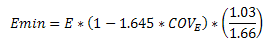
COVE (the coefficient of variation in modulus of elasticity) comes from Table F1 in Appendix F.
Wood Code Check Results
Access the Wood Code Checks Spreadsheet by selecting the Code Check spreadsheet from the Results toolbar on the Explorer Panel and then clicking the Wood tab.

Click on image to enlarge it
Code Checks
The final result of the design solution are the code check values (ratios of actual stress to allowable stress). So, if these values are less than 1.0, the member passes. If they are greater than 1.0, the member fails.
- If the value is greater than 9.999 it will be listed as "9.999".
- The Member Detail Report gives a more detailed view of the values used to perform the code check.
- See Results View Settings - Members to learn how to view the code check results graphically.
The UC Max value represents the combined bending and axial force stresses. The governing equation that was used to calculate the UC Max value is listed at the far right of the spreadsheet in the Eqn column.
The
The Loc fields that are to the right of the code check fields tells at what location the maximum code check occurs measured from the I-joint location of the member.
The Dir field tells us in which local member direction the maximum shear is occurring (y or z).
Capacity Values
The values (Fc', Ft', Fb1', Fb2', Fv') are the factored allowable stresses per NDS wood member design.
- For the bending stresses (Fb), Fb1' is for bending about the local z-z axis (the strong axis) and Fb2' is for bending about the local y-y axis (the weak axis).
- RB is the adjustment factor described by Eqn. 3.3-5 of the 2018 NDS Specification. This is a slenderness ratio that is not allowed to exceed 50.
- CL is the beam stability factor calculated using Eqn. 3.3-6 of the NDS Specifications.
- CP is the column stability factor calculated using Eqn. 3.7-1 of the NDS Specifications.
The values (Pr, Tr, Mr, Vr/Wr) are the allowable forces per CSA O86 wood member design. These will only be visible when you have selected the CSA O86-09: Ultimate or CSA O86-14: Ultimate as your wood design code in .Model Settings.
- Reference equations are reported in the member detail report for the calculation of each capacity value.
- The Vr/Wr shear resistance value for glulams depends on the CV value. Unless manually entered by the user, this value is always assumed 1.0.
- This value is called "Vr" in the 2009 version of the code and "Wr" in the 2014 version of the code.
- The Pr, axial compressive resistance for sawn lumber members will have a 75% reduction taken into account (per clause 6.5.6.4.3) for bolted multi-ply members.
- The Tr, axial tensile resistance for glulams only considers the gross area of the member when calculated per clause 7.5.11.
- The glulam material Table 7.3 in the CSA O86-09 does not include weak axis bending or shear values. Per the commentary to clause 7.5, glulams will use the sawn lumber values for the glulams species' grade No. 2 listing in Table 6.3.1A.
Finally, the Equation controlling the
code check is listed. For NDS wood member design, this will be either Eqn. 3.9-1 or 3.9-3. Eqn. 3.9-2 is
not checked since this equation includes the tension stress in a beneficial
(non-conservative) manner. All other requirements in Section 3.9
are also checked, such as fc < FcE1, etc. To see ALL the adjustment
factors and other information used to calculate the factored allowable
stresses, please go to a detail report for the member in question.
![]()
Click on image to enlarge it
- For Enveloped results the combination that produced the listed code and shear checks is given in the "LC" column. The other values are the corresponding values and are not necessarily the maximums across all the combinations.
- Moving Load results are enveloped and the governing load combination and step location is shown for each result value under the "LC" column. The first number is the load combination, the second is the step number: (load combination - step number). See Moving Loads to learn more.
Special Messages
In some instances code checks are not performed for a particular member. A message explaining why a code check is not possible will be listed instead of the code check value. You may click the cell that contains the message and look to the status bar to view the full message. Following are the messages that may be listed:
Code Check Not Calculated
This is the general message displayed when code checks were not performed
for a member. It could mean that you have not selected a Design Code in
RB value is greater than 50
Section 3.3.3.7 of the NDS code limits the slenderness ratio RB to a maximum of 50. Similarly, clause 7.5.6.4.3 of the CSA O86 limits CB to a maximum of 50. You will need to reduce the effective span length, increase the thickness of the shape, or reduce the depth of the shape.
le/d is greater than 50
Section 3.7.1.4 of the NDS code limits the column slenderness ratio of Le1/b or Le2/d to a maximum of 50. You need to reduce your effective length by reducing the actual length between supports or changing the effective length factor “K”. You can also use a thicker shape.
fc is greater than FcE1
Section 3.9.2 of the NDS code limits the actual axial compressive stress to be less than the term FcE1. This term is approximately the Euler buckling stress for buckling about the strong axis of the member. (Buckling is in the plane of bending)
fc is greater than FcE2
Section 3.9.2 of the NDS code limits the actual axial compressive stress to be less than the term FcE2. This term is approximately the Euler buckling stress for buckling about the weak axis of the member. (Buckling is in the plane of bending)
fb1 is greater than FbE
Section 3.9.2 of the NDS code limits the actual strong axis bending compressive stress to be less than the term FbE. This term is approximately the lateral buckling stress.